
Queen's has an opportunity to save money and make better use of energy through conservation and efficiency.
Energy costs, although subject to some market fluctuations, continue to rise. The annual campus utility budget is now approximately $18 million.
In addition, traditional methods of energy production rely heavily on fossil fuels, of which consumption entails negative environmental impacts. In particular, greenhouse gas (GHG) emissions associated with the burning of fossil fuels are contributing greatly to global climate change.
The University is seeking alternative forms of energy production, such as geo-exchange wells, and major infrastructure upgrades and retrofits as we strive toward our target of becoming carbon neutral by 2040.
Climate Action Plan (PDF 4.8 MB)Conservation Programs
Cogeneration plants, or combined heat and power plants, simultaneously generate both heat and power from the same process. One consequence of the second law of thermodynamics is that when electricity is generated from a high-temperature source, be it combustion, nuclear or whatever, only a portion of the heat drawn can be converted to electricity. The rest must be disposed of in some low temperature reservoir. Large generating stations typically get rid of excess heat either by using cooling towers, by transferring the heat to the atmosphere, or by using water flow from a nearby river or lake. It is the norm in Canada to do this. But new technologies allow us to make use of this extra heat instead.
Approximately 60% of the energy from large coal burning power stations, and approximate 70% of the energy from nuclear stations, is not used. And a great deal more fuel must then be burned to heat houses, factories and commercial buildings. Elsewhere in the world, and particularly in northern Europe, the heat produced is used either in industrial plants, or in district heating systems which distribute heat to communities through pipes carrying steam or hot water. This method of heat distribution reduces greatly the primary energy requirements of the society, and reduces the environmental effects of energy production.
In Canada, cogeneration has begun to appear in industry, where the industry itself utilizes both the electricity and the heat. Large buildings, such as hospitals or hotels, have also begun to install gas turbines or other devices to produce both electricity and heat. The European practice of utilizing the heat from large central power stations through district heating is still rare in North America.
Queen's University, like most Canadian institutions, has used combustion for campus heating. Now it has replaced these units with cogenerating units, which can provide all of the steam needed for campus heating and generate much of our electrical needs at the same time. This unit is heavily instrumented, and the data made available below for studying both the thermodynamics, the economics, and the environmental impacts of such units.
Enthalpy Wheel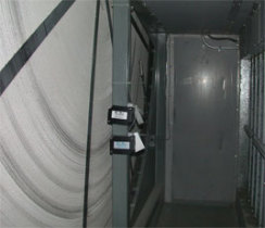
An enthalpy wheel exchanges heat and humidity from one air-stream into another. Rather than discard used building air, an enthalpy wheel salvages useful energy and transfers it to incoming, fresh air. This saves energy by reducing the need for cooling in the summer and heating in the winter.
Enthalpy wheels are becoming common in HVAC systems. There are currently two other wheels in use on the Queen's campus (in the Cancer Research Centre and in the new residences).
The IL Centre's enthalpy wheel is a large, turning disc made out of an aluminum honeycomb material that is coated in desiccant. The aluminum expands when it is heated, and carries that energy around with it as the wheel rotates. When it hits a cooler air-stream, the aluminum contracts and the heat energy is released into the air.
The exchange of humidity depends upon vapour pressure. When warm air flows through the wheel it heats up the desiccant material. The vapour pressure of the desiccant is raised until it is higher than the vapour pressure of the air in the opposite air-stream. When the wheel turns into that air-stream, the water evaporates into it. The result is that cooler air is humidified and warmer air is dehumidified.
The wheel is three meters (ten feet) in diameter, and sits between the main incoming and outgoing air-streams of the IL Centre's air-handling system. It rotates through the incoming and outgoing airstreams at a rate of one to six revolutions a minute, depending upon outside air temperature and humidity.
When a section of the wheel passes through the warmer air stream, the heat is transferred to the aluminum honeycomb on the wheel, and moisture is transferred to the desiccant. When that portion of the wheel rotates into the cooler air stream, the honeycomb cools and releases its heat into it, and the desiccant releases its moisture. The supply air is warmed and humidified in the winter and cooled and dried in the summer. The device is effective all year around at pre-conditioning the outdoor air.
When the temperature outside is near room temperature, the wheel shuts down, and air travels through a bypass duct. When the wheel can't save energy for the heating and cooling systems -- the fans that blow air into and out of the unit consume a lot of power -- energy is conserved by powering it down.
Purge Sector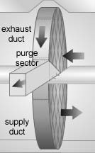
While the wheel exchanges heat and humidity, it shouldn't be able to exchange anything else, like toxins or contaminants, from the exhaust air into the incoming air. Seals maintain a boundary between the ducts where they meet the enthalpy wheel. To increase effectiveness, the incoming air is at a higher pressure than the outgoing air, so if air does flow between the ducts, the fresh air will want to flow into the exhaust air-stream rather than the other way around.
Enthalpy wheels also remove contaminants from the air. A purge sector, a small area that the wheel rotates into between the incoming and outgoing ducts, blows any exhaust air from the wheel media before it rotates into the supply air duct. Purge sectors have helped lower cross-contamination from 4 or 6 percent to 0.04 percent, and have made enthalpy wheels suitable for sensitive environments such as chemical laboratories and hospitals.
Molecular sieves prevent molecules larger than a specific size from being absorbed into the desiccant of the wheel. The common sieve size is three angstroms, as this allows the 2.8-angstrom water molecule to be absorbed while screening larger airborne contaminants.
Conservation Projects
Labs are Energy Intensive Buildings
Research is an energy intensive activity. Ensuring a safe lab environment requires much more ventilation than typical teaching and working spaces. Kingston’s climate with cold winters and hot humid summers mean a lot of work for the heating and cooling systems to maintain a comfortable indoor environment.
Exhaust air from lab rooms and their fume hoods cannot be recycled within the building the way air from an office can be, it must be sent directly outdoors. Since the volume of air inside a building is always the same this means the same volume of “make-up air” must be brought in from outdoors to replace the exhaust air.
The make-up air must be heated or cooled before it can be blown into the rooms in the building. On a cold Kingston winter day the heating and ventilation system may have to take air from outside at -20 °C and heat it to 25°C, a difference of 45°C! Doing this takes a massive amount of energy, and is a main reason why lab buildings are so energy intensive.
Optimization of Fume Hood Exhaust
Ensuring that the ventilation system is properly calibrated so each fume hood is pulling only the required amount of air for safe operation, and that labs are able to reduce flow when not in use is essential to efficient operation.
Advanced controls allow precise control of fume hood exhaust flow. The fume hoods in Chernoff Hall will have a new digital control system installed to allow exhaust air valves to vary the flow of exhaust and make-up air. The labs will now operate in occupied or unoccupied mode based on sensors located throughout each room. When there is no one working in a lab and additional sensors confirm all fume hood sashes are closed, the room will enter an unoccupied mode with reduced airflow.
All of the fume hoods in Chernoff Hall will also be calibrated to their manufacturer recommended flow rate and confirmed for safe operation using standardized lab test procedures.
Optimization of the fume hood exhaust at Chernoff is expected to save 781 tonnes of CO2 emissions.
Heat Recovery
Another way to improve the efficiency of lab buildings is to add a heat recovery system. There are several types, but they all move heat from the exhaust air to the incoming fresh air. This reduces the amount of new heat energy that must be used to bring the incoming fresh air up to an acceptable temperature.
Chernoff Hall had a glycol run-around loop heat recovery system added in 2017 that is saving 634 tonnes of CO2 emissions per year. This same type of system will be installed in the Biosciences Complex.
Using two glycol coils (very similar to automobile radiators), a solution of glycol and water is pumped between the exhaust airstream and the incoming airstream. In the winter the exhaust air heats the glycol in one coil which is then pumped to the fresh air intake, where the air flows over the other coil and picks up that heat to preheat the incoming air. This reduces the amount of heating that needs to be done using fossil fuels before the fresh air can be distributed to the building.
The new heat recovery system in the Biosciences Complex will reduce carbon emissions by 202 tonnes.
Queen's is continuously pursuing lighting retrofit projects for energy conservation. It is estimated that 17% of a buildings energy usage is attributed to lighting loads. Typical lighting retrofits will provide 40% - 60% of a reduction in electrical use, this makes lighting retrofit projects very feasible since they can provide such high energy savings.
Light Emitting Diodes (LED's) are proving to be the way of the future when it comes to lighting technologies. This form of lighting provides consumers with a high lumen output at the cost of minimal electricity. LED's also typically provide 50,000 hours to 70,000 hours of light before failing, providing consumers with a very efficient and sustainable form of lighting. Queen's will continue to eliminate fluorescent and high intensity discharge lighting when possible. There is an estimated 520 kW's of inefficient florescent lighting that will be phased out over time. This kW load can be reduced to 200 kW's using LED's. That makes for a 60% reduction in the Universities lighting load! Check out some of our lighting retrofit projects below to see how much of a difference LED's can make.
Coastal and Geological Engineering Laboratory Lighting Upgrade
The Geological and Coastal Engineering Lab recently underwent a facility wide lighting upgrade. This lighting upgrade replaced old and inefficient High intensity discharge lighting fixtures with high bay LED fixtures. This retrofit lowered the buildings lighting load by 14,000 kWh's annually. This equates to 33% of the buildings electricity usage and lowered the facilities electricity bill by $5,600! The sustainability team was able to eliminate unnecessary lighting loads in the facility while doubling the lumen output. While undergoing this retrofit, the facilities average illuminance increased from 20 foot-candles to 40 foot candles.
Queen's also installed advanced occupancy and scene control systems as a part of this lighting upgrade. This control system allows the occupants to create scenes which control the amount of light that the research spaces are receiving. All lighting scenes can be customized to suit the needs of various occupants. Occupancy control also lowers the light levels to 5% when it senses vacancy.
Parking Garage Lighting Upgrade
The affected parking garages were:
- Queen's Center parking
- Goodes Hall Parking
- Stuart St Parking
- Union St. Parking
Residence Lighting Upgrade
During the summer of 2019, Queen's University initiated a large scale lighting retrofit across residences. The three affected buildings were Waldron Tower, Adelaide Hall, and Chown Hall. Not only did this project eliminate old and obsolete lighting technologies, but nearly doubled the lighting levels within these residence buildings.
Occupancy sensors were also installed in the Waldron stairwells and hallways. These sensors will dim the lights levels when the spaces are unoccupied. Occupancy sensing is a trending technology due to its simplicity, and effective savings. Occupancy control in Waldron tower was shown to decrease lighting loads by 25% within hallways.
This lighting upgrade will to reduce the electricity usage of the university by 67,000 kWh, and lower the greenhouse gas emissions by 2.6 tonnes annually. This volume of greenhouse gases is the equivalent of burning 1,100 litres of gasoline annually! The reduction in carbon emissions will also contribute to the sustainability team’s goal of becoming carbon neutral by the year 2040.
New District Heating System
Summer 2019 marked Queen's Universities first step away from the district energy steam system, taking on a $10.5 million retrofit that would replace an inefficient 46-year-old underground steam line with a new system.
Queen`s currently uses steam in order to provide heating to it`s facilities. This steam is produced at the Central Heating Plant along King st. w. This plant houses three large boilers which have the capacity of producing 150,000 lbs of steam each, as well as two cogeneration units which have the capacity of producing 70,000 lbs of steam and 7 megawatts each,
This steam system was a good method of providing heating to the university, but has slowly grown less effective over the years in comparison to newer heating technologies. The university has a plan to transition all of its heating systems to a hot water system which is much more efficient. West Campus was the first campus to make this transition by installing three large condensing boilers at its Refrigeration Plant.
Green House Gas Reductions
Changing the west campus steam lines over to a new hot water steam system is estimated to reduce the Universities GHG footprint by 1,500 metric tonnes of carbon dioxide. This is the equivalent of 3.7 million miles driven by an average passenger vehicle, or 170,000 gallons of gasoline.
On top of green house gas reduction, this retro fit also lowers operational costs significantly. The University now consumes less natural gas with the incorporation of a more efficient heating system. There is also a $30,000 decrease in carbon taxes this year as a result of consuming less natural gas. This cost avoidance is expected to increase to $75,000 per year over the next three years.
Future Implementation of a New District Energy System
Queen`s University plans on slowly transitioning away from their steam district energy system, West Campus was only the first part of campus to see this change happen. In the future, the University plans on installing the proper infrastructure for a hot water distribution system, and replace the steam boilers at the Central Heating Plant, with high efficiency condensing boilers, similar to what was installed in West Campus.
Through a variety of funding programs, CAPit provided an opportunity to complete significant energy conservation renewal projects involving campus infrastructure and facilities. Completion of these projects has benefited the university in three major ways:
- Reduction of energy consumption and GHG emissions
- Generation of savings within the utility budget
- Replacement of outdated equipment and reduction to the deferred maintenance liability.
By the numbers
- 2800 tonne carbon reduction
- 185,000 m3 water reduction
- 66 campus buildings
- 170 conservation measures
- 1147 toilet retrofits
- 61 urinals retrofits
- 353 shower head replacements
- 1523 faucet moderators installed
- 1666 LED retrofits
- 1364 upgraded ballasts
- 9216 fluorescent tube replacements
Program timeline
- The first study was done in 2014
- Completed the concept report in 2015
- Started construction in 2016
- Completed construction in 2018
The program was divided into two distinct phases. The first phase involved an energy performance contract and the second phase convert west campus to a district energy system.
Phase 1
The first phase included the development of an ASHRAE Level One Energy Audit of campus and a summary report of the entire campus’ energy consumption, a study of past utility bills, an energy profile for buildings and a list of energy conservation measures, savings potential, high level implementation cost, and potential utility incentives. The audit included the majority of primary campus buildings as well as the supporting infrastructure such as the central heating plant and steam distribution system.
Based on the list of energy conservation measures, the first phase also saw the implementation of over 9000 fluorescent tube light replacements, 1666 LED light retrofits, and over 3000 upgrades to toilets, showers, and faucets. Along with 170 other conservation measures, including building envelope repairs and climate control improvements, these upgrades resulted in a 2800 MTCO2e reduction, and a 185,000 m3 reduction in water usage across 66 buildings at Queen's University.
Funding for phase 1 was secured from the savings to the utility budget through a performance contract with Honeywell, an Energy Service Company (ESCo).
Phase 2
The second phase of CAPit, completed in 2018, included the West Campus District Energy Conversion Project. The project involved the decommissioning of a 2.5 km steam line that runs underground along Union Street from the Central Heating Plant on main campus to the West Campus, and the installation of a new, more efficient boiler system. In contrast to phase 1, the funding for this project was secured as part of the 2017-2018 Ontario Government’s Greenhouse Gas Retrofits program (GGRP).
Lighting Measures
T8 Fluorescent Lighting – Where existing fixtures are in good shape, lamps and ballasts are replaced with new high efficiency T-8 lamps and electronic ballasts. Where existing fixtures are in poor shape, fixtures are replaced with new luminaires containing new T8 lamps and electronic ballasts. As part of the upgrade process, the existing ballasts and lamps are removed from the fixture and disposed of in an environmentally friendly manner.
Advantages of T8 fluorescent lighting, when compared to incandescent lighting, include:
- Fluorescent bulbs have a longer lamp life lasting up to 20 times longer
- Tend to burn out less after continuous use
- Lamps do not give off heat making them ideal for area lighting or heat sensitive areas
- More energy efficient
LED lighting – selected indoor light fixtures will be replaced with LED style lamps. A light-emitting diode (LED) is a solid state lighting system that creates light far more efficiently and with less wasteful heat produced. Existing incandescent and compact fluorescent lamps are replaced with new LED bulbs. In some areas new LED fixtures will be installed to replace old fixtures that are in poor shape.
Key advantages of LED lights, especially compared to incandescent lighting, are:
- low energy consumption/reducing ecological impact
- low maintenance requirements
- small size
- long lifetime – can last up to 25 times longer than incandescent bulbs
- typically more rugged
- fast switching time between on/off cycles
- low heat output
Building Automation Measures
The building automation system (BAS) will be upgraded or expanded using Direct Digital Control (DDC) systems to allow better control of heating, ventilation, air conditioning and other mechanical equipment in selected buildings. A Building Automation System (BAS) controls building heating, ventilation, air conditioning, and other systems. It provides the building operator the ability to monitor and troubleshoot the operation of associated equipment. Connecting multiple mechanical sub-systems, rather than operating them independently, optimizes building operation, lowers energy use, improves occupant comfort and allows off-site building control.
Room temperature and air supply will be automatically controlled by the BAS. Mechanical equipment will be scheduled to turn on and off based on building occupancy schedules. Override buttons will be installed where applicable to start fan systems for occasional after-hours use.
Air Handling Unit Measures - An air handling unit (AHU) is a device used to regulate and circulate air as part of a heating, ventilation and air conditioning system. An air handler connects to ductwork systems that distribute conditioned air through the building and returns it to the AHU. The AHU contains a fan, motor, heating or cooling coils, filters, and dampers. Various components of air handling units will be upgraded to provide better control of air flow to match occupancy requirements.
Zone Dampers - Throughout the university there are several air handling systems that provide ventilation to multiple areas in a building with different occupancy schedules and hours of operation. In order to provide the required amount of ventilation to each unique area, zone dampers are used to isolate shorter occupancy zones from longer ones. Motorized zone dampers will be installed in the air distribution ductwork that will be controlled by the BAS. Motion detectors, occupancy schedules and temperature sensors located in zones will control the damper operation.
Variable Frequency Drives - A variable frequency drive (VFD) is a type of motor controller that variates the frequency supplied to an electric motor. If an application doesn’t need an electric motor to run at full speed, the VFD can slow down the motor by reducing the frequency to just meet the requirements of the electric motor load, thus not using unneeded energy.
VFDs will be installed on the supply and return fan motors to control air flow rates. Existing fan motors will be replaced with high efficiency models.
Air Handling Unit Heat Recovery - In buildings with a large amount of exhaust and fresh supply air there is the opportunity to reuse energy exhausted from the building to pre-heat or pre-cool outside air. This involves adding a heat recovery system between the air intake and the air exhaust ducts.
Steam Traps
For buildings with steam heating systems, steam traps prevent steam from passing through the system by ensuring that steam has condensed back to liquid water before returning to the heating plant. Steam traps can leak or fail allowing hot steam to pass through the system or escape to the atmosphere wasting heating energy. All steam traps in the buildings will be tested and failing traps will be replaced with new ones. This can significantly reduce energy loss in heating systems.
Water Conservation Measures
Plumbing Fixtures - There are many water efficient technologies available today that can significantly reduce water use as well as operating and maintenance costs. Low-flow plumbing fixtures offer water efficiency without compromising their effectiveness. New low-flow plumbing fixtures will be installed in select areas including aerators, shower heads, toilet tanks, flush valves and urinals.
Process Water Systems - Many refrigeration and cooling systems use a significant amount of city water during their operation. Heat is removed from the refrigeration systems using city water which is then dumped down the drain which is wasteful. These systems will be retrofitted to a closed loop water cooling system that reuses the water or to air cooled system.
Building Envelope Measures
Air leakage is uncontrolled migration of conditioned air through the building envelope and is caused by pressure differences due to wind, stack effect and mechanical system imbalances. Air leakage represents a significant source of heat loss or gain through the building envelope. In addition to the potential for energy savings, uncontrolled air leakage can affect occupant comfort and air quality and damage the building’s structural integrity due to moisture migration.
Controlling air leakage involves sealing gaps, cracks and holes with materials and systems that create a continuous “air-tight” barrier around the building envelope. Primary areas of focus are doors, windows, wall penetrations and roof/wall joints which will be sealed as part of this project.
Report Library
- Conservation and Demand Management Plan 2019 (PDF, 3.5 MB)
- Annual Energy and GHG Report 2020 (PDF, 568 KB)
- Annual Energy and GHG Report 2019 (PDF, 563 KB)
- Annual Energy and GHG Report 2018 (PDF, 181 KB)
- Annual Energy and GHG Report 2017 (PDF, 562 KB)
- Annual Energy and GHG Report 2016 (PDF, 563 KB)
- Annual Energy and GHG Report 2015 (PDF, 562 KB)
- Annual Energy and GHG Report 2014 (PDF, 567 KB)
- Annual Energy and GHG Report 2013 (PDF, 569 KB)
- Annual Energy and GHG Report 2012 (PDF, 71 KB)
- Annual Energy and GHG Report 2011 (PDF, 98 KB)
- Queen's Carbon Footprint Report, 2022 (PDF, 12 MB)
- Queen's Carbon Footprint Report, 2021 (PDF, 8.8 MB)
- Queen's Carbon Footprint Report, 2020 (PDF, 6.6 MB)
- Queen's Carbon Footprint Report, 2019 (PDF, 3.5 MB)
- Queen's Carbon Footprint Report, 2018 (PDF, 3.0 MB)
- Queen's Carbon Footprint Report, 2017 (PDF, 3.3 MB)
- Queen's Carbon Footprint Report, 2016 (PDF, 1.2 MB)
- Queen's Carbon Footprint Report, 2015 (PDF, 3.5 MB)
- Queen's Carbon Footprint Report, 2014 (PDF, 1.1 MB)
- Net-Zero Innovative Residence Design, Civil Engineering Capstone 2024 (PDF, 3.4 MB)
- Wastewater Heat Recovery Team 31, Mechanical Engineering Capstone 2024 (PDF, 2.4 MB)
- Wastewater Heat Recovery Team 30, Mechanical Engineering Capstone 2024 (PDF, 1.7 MB)
- Solar PV, Civil Engineering Capstone 2023 (PDF, 2.9 MB)
- Solar Shading, Civil Engineering Capstone 2023 (PDF, 3.8 MB)
- Sustainable Landscapes, Civil Engineering Capstone 2023 (PDF, 8.0 MB)
- Traffic Engineering, Civil Engineering Capstone 2023 (PDF, 8.7 MB)
- Queens Pathway Standard Recommendations, School of Urban and Regional Planning 2022 (PDF, 10.3 MB)
- Embodied Carbon in New Construction, Civil Engineering Capstone 2022 (PDF, 11.4 MB)
- Green Roofing for Campus Buildings, Civil Engineering Capstone 2021 (PDF, 0.7 MB)
- Rehabilitation of 5th Field Company Lane, Civil Engineering Capstone 2021 (PDF, 19.7 MB)
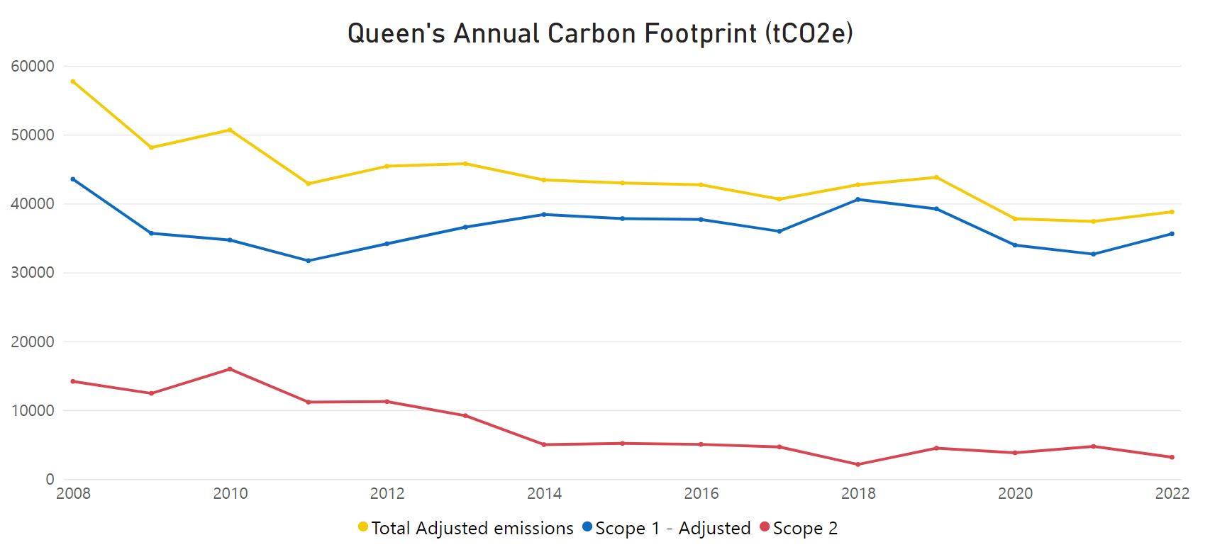
GHG Inventory Overview
The campus carbon footprint or GHG inventory includes emission sources attributable to the university and follows established reporting protocols.
The inventory includes all scope 1 (direct) and scope 2 (indirect) emission sources. Additionally, the emission sources included cover all facilities that are either owned or operationally controlled by the university within Ontario.
The campus inventory includes two final emission values. The total emissions represent the 'all-in' carbon emissions for Queen's and its central heating plant. Our adjusted total reflects the campus emissions attributable directly to university operations. It is necessary to track two values because a portion of the steam generated by the campus central heating plant also supplies three hospital buildings: 355 King St. West (former St. Mary's of the Lake site), Hotel Dieu and Kingston General Hospital. The hospital consumption accounts for roughly 30% of the steam production. As the hospitals are outside of the university's operational control, the adjusted campus value is the basis for which reduction targets are set.
Calculating Emissions
A GHG inventory is a tally and calculation of the emissions and removals that occur within a specific area.
The Intergovernmental Panel on Climate Change (IPCC) established reporting protocols to help ensure consistency in emission reporting. These protocols lay the groundwork by providing common definitions, defining scope and outlining calculation methodology.
Greenhouse gas (GHG) emissions typically refer to the six gases identified by the IPCC and used in the Kyoto Protocol: carbon dioxide (CO2); methane (CH4); nitrous oxide (N2O); hydrofluorocarbons (HFCs); perfluorocarbons (PFCs); and sulphur hexafluoride (SF6). Scientists have determined that these gases have the greatest impact on climate change.
The calculation results are expressed in terms of carbon dioxide equivalents (CO2e). This is a universal unit of measure that indicates the global warming potential (GWP) of each of the six greenhouse gases, expressed in terms of the GWP of one unit of carbon dioxide. Inventory results are often referred to as a carbon footprint.
Within inventories the IPCC has defined three categories of emission sources, including;
- Scope 1 emissions are direct source emissions owned or controlled by institutions and miscellaneous leaks like fuel burning in heating plants and potential chemical seepage from a fire suppression system
- Scope 2 emissions are indirect emissions from the generation of purchased utilities like electricity
- Scope 3 emissions are all other indirect emissions like those associated with supply chain, employee travel, waste etc.